When it comes to e-ink displays, Waveshare is a rare manufacturer that allows you to buy displays of any size. Advertised as ESP32, Arduino and Raspberry Pi compatible, they are in fact compatible with any development board exposing the SPI protocol.
Since Raspberry Pi boards have become hard to find in recent months, we’ll take a look in this article at how to use another Linux-based board to run a Waveshare display.
Display communication protocol
Waveshare’s e-ink displays are driven by the SPI protocol. Like USB or I²C, this is a common standard for communication between a machine and a peripheral.
To communicate, the protocol uses 3 wires + 1 wire per peripheral:
SCLK(orSCKorSCL) is the clock signal to synchronize communication;MOSI(orSDOorSDA) is the data flow from the machine to the peripheral;MISO(orSDI) is the data flow from the peripheral to the machine.
Several devices can share the SPI bus, the 3 wires described above. To keep track of who the information is intended for, there is an additional wire for each peripheral. With 3 devices on the SPI bus, we’ll have 6 wires: the 3 bus wires, shared, and 1 wire per device, non-shared.
This additional wire, called CS for Chip Select (or SS), is powered when the machine wishes to talk to the designated device.
Only 1 device is active at a time, to avoid collisions on the bus (imagine two devices sending two separate messages at the same time… on the same wire).
A device only talks and listens when its CS is low (at 0).
When a device sends or receives data, it synchronizes to the clock frequency transmitted by the machine on the SCLK wire.
At clock top, 1 bit of information can be read from MISO and MOSI.
The machine and the peripheral can send data simultaneously, since we have 1 wire dedicated to transmission and 1 wire dedicated to reception.
In the case of Waveshare displays, only uplink communication to the peripheral is used; the display will never respond on the SPI bus.
There is therefore no wire for MISO.
To communicate its status, it uses dedicated wires.
Other wires used
In addition to the power supply (+3.3 V and ground) and the wires used for the SPI protocol, 3 wires complete the communication:
DC: 0 when sending commands on the SPI bus. Set to 1 when sending data.RST: when this wire is set to 0, it causes the screen to restart, resetting all its registers. It is reset to 1 to start using it.BUSY: the chip controlling the screen uses this wire to indicate whether the screen or controller is busy, performing an action (when set to 0) or ready to receive information (when set to 1).
With these specifications well established, there’s nothing to limit us to the Raspberry Pi alone!
Recognizing a compatible card
To be used with the display, the board must expose an SPI bus on its GPIOs, and you must have 3 generic slots available in addition to 3.3 V and ground.
All boards, recent and old, expose these interfaces.
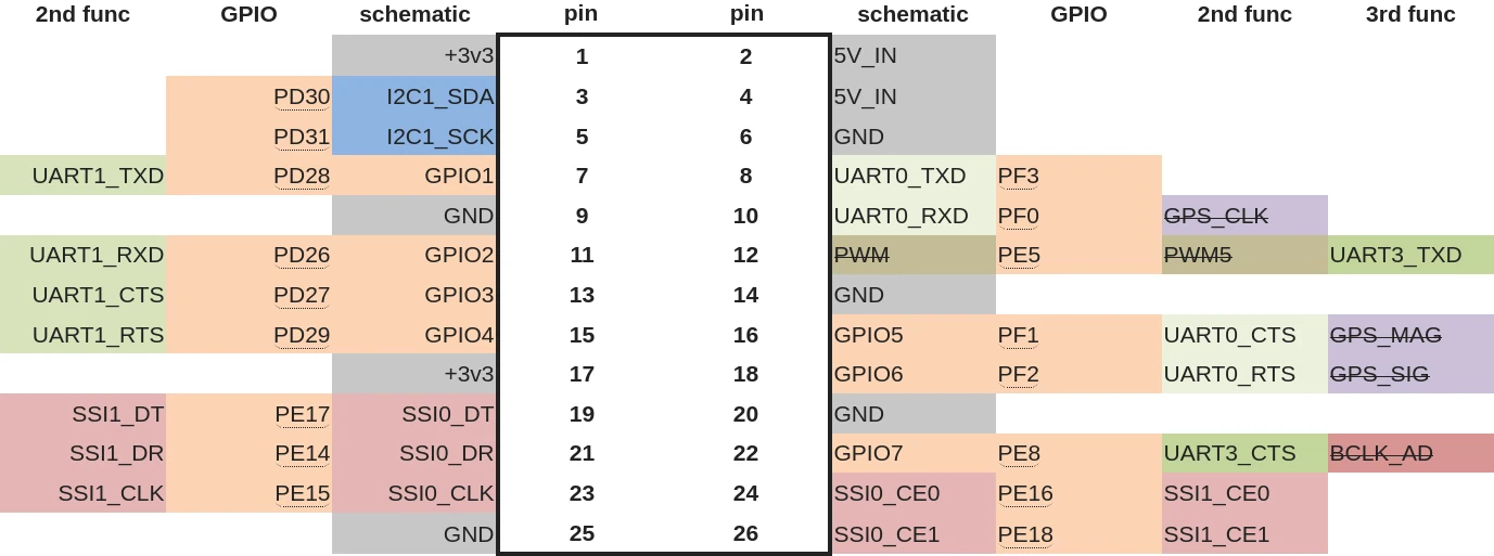
For example, here’s the pin assignment for the Pine64:
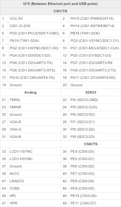
And for the Cubieboard :
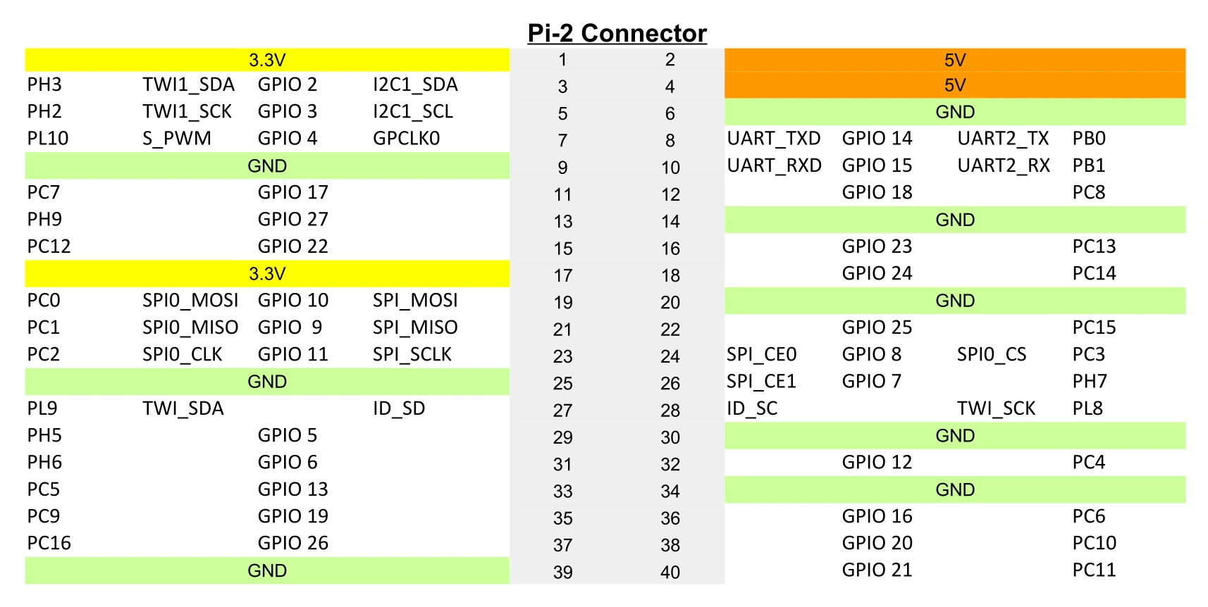
Some boards have GPIOs identical to those on the Raspberry Pi, so you can place the supplied HAT directly on them. When the pin organization is different, you’ll have to cable it manually.
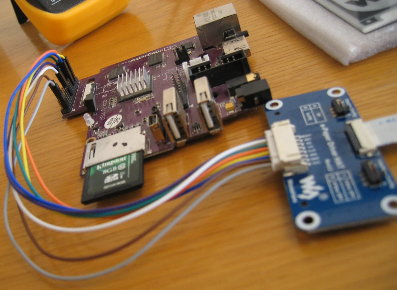
I used a MIPS Creator CI 20 board:
Here is the wiring:
Linux configuration
The Waveshare documentation suggests using the utilities supplied with Raspbian. We don’t have the same simplified utilities, so we’ll see how to do it directly.
Activate SPI
Usually, a kernel module is loaded to communicate with an SPI-connected device.
This module will then create an abstraction layer and expose the abstraction in the /dev folder.
Here, we don’t have a kernel module dedicated to the screen; in fact, the program we’re about to launch, the Waveshare demo, communicates directly via SPI.
It’s as if we’d written a program to read and write to a USB stick by sending the raw USB commands, rather than having the kernel display the device under /dev/sdb.
In order to drive the SPI bus from a user-space program, we’ll need to tell our kernel that it must use the spidev driver to manage the bus in question.
If you’ve compiled your kernel yourself, make sure you have this module:
42sh$ zgrep SPI_DEV /proc/config. gz
CONFIG_SPI_SPIDEV=y
The kernel obtains information on the devices and modules to be used by consulting a file called Device Tree, specific to each SBC.
Generally, when a device is not in use, it is marked as disabled in the Device Tree.
If you don’t have a /dev/spidev* file, you’ll have to start by enabling it.
Activation using a Device Tree Overlay
The Raspbian tool that activates the SPI bus in the Waveshare documentation will in fact activate a pre-designed Device Tree Overlay.
We can do the same by creating our own Device Tree Overlay. The aim is to activate our SPI bus.
From the basic DTB file for our board, we should have somewhere (potentially in the #include) a block like this:
spi0: spi@10043000 {
	compatible = "ingenic,jz4780-spi";
	reg = <0x10043000 0x1c>;
	#address-cells = <1>;
	#size-cells = <0>;

	interrupt-parent = <&intc>;
	interrupts = <8>;

	clocks = <&cgu JZ4780_CLK_SSI0>;
	clock-names = "spi";

	dmas = <&dma JZ4780_DMA_SSI0_RX 0xffffffff>,
	       <&dma JZ4780_DMA_SSI0_TX 0xffffffff>;
	dma-names = "rx", "tx";

	status = "disabled";
};
We can see that it is disabled (status = "disabled").
In relation to our pins, if these are indeed the ones we wish to use, we will then establish the following overlay (my_spidev.dts) :
/dts-v1/;
/plugin/;

&spi0 {
    status = "okay";

    spidev0: spidev@0{
		compatible = "spidev";
		reg = <0>;
		#address-cells = <1>;
		#size-cells = <0>;
		spi-max-frequency = <500000>;
	};
}
Now let’s compile our overlay :
dtc -O dtb -o MY_SPIDEV.dtbo my_spidev.dts
We then place it in our boot partition, alongside the kernel and our dtb.
For example:
mv MY_SPIDEV.dtbo /boot/overlay/MY_SPIDEV.dtbo
Then reboot and load this overlay in u-boot:
# What is currently done
load mmc 0:1 0x820000000 ci20.dtb
fdt addr 0x82000000

# Steps to add after device tree loading
load mmc 0:1 0x83000000 overlays/MY_SPIDEV.dtbo
fdt resize 8192
fdt apply 0x83000000

# Then boot as usual
bootz ...
Once we’ve tested that it works, we can add it to the startup script.
Doing without an SPI bus
If you don’t have an SPI bus available, you can still use GPIO pins and dedicate them to this purpose.
To do this, we’ll use the spi-gpio kernel module, in addition to spidev.
First of all, let’s make sure we have its support:
42sh$ zgrep SPI_GPIO /proc/config.gz
CONFIG_SPI_GPIO=y
Here’s the overlay we could write to simulate an SPI bus on pins 19, 21, 23, 24 and 26:
/dts-v1/;
/plugin/;

#include <dt-bindings/gpio/gpio.h>

spi_gpio {
    compatible = "spi-gpio";
    #address-cells = <1>;
    #size-cells = <0>;
    gpio-sck = <&gpf 15 GPIO_ACTIVE_HIGH>; /* PE15 */
    gpio-miso = <&gpf 14 GPIO_ACTIVE_HIGH>; /* PE14 */
    gpio-mosi = <&gpf 17 GPIO_ACTIVE_HIGH>; /* PE17 */
    num-chipselects = <2>;
    cs-gpios = <&gpf 16 GPIO_ACTIVE_HIGH &gpf 18 GPIO_ACTIVE_HIGH>; /* PE16, PE18 */

    spidev@0 {
        compatible = "spidev";
        reg = <0>;
        spi-max-frequency = <1000000>;
    };
};
The overlay is applied at startup, as described above.
In both cases, it is also possible to make the changes directly in the original DTS file and replace the DTB used to boot the board. You’ll have to do this again each time you update the kernel.
Configuring dedicated GPIOs
We’ve seen that the display uses 3 GPIOs in addition to the SPI bus.
In my case, I chose to use pins 18 (PF2), 11 (PD26) and 22 (PE8).
Let’s declare them with:
# BUSY: PF2
echo 162 > /sys/class/gpio/export

# RST: PD26
echo 122 > /sys/class/gpio/export
echo out > /sys/class/gpio/gpio122/direction

# DC: PE8
echo 136 > /sys/class/gpio/export
echo out > /sys/class/gpio/gpio136/direction
Adapting the demo code
The Waveshare demo expects to run on a Raspberry Pi, so there are a number of hard-coded elements. In addition, it makes use of a Python dependency that doesn’t work outside this platform.
Here are the implementation I’ve made to adapt the code to my needs:
--- a/RaspberryPi_JetsonNano/python/lib/waveshare_epd/epdconfig.py
+++ b/RaspberryPi_JetsonNano/python/lib/waveshare_epd/epdconfig.py
@@ -230,6 +230,89 @@ class SunriseX3:
         self.GPIO.cleanup([self.RST_PIN, self.DC_PIN, self.CS_PIN, self.BUSY_PIN], self.PWR_PIN)


+class CreatorCI20:
+    # Pin definition
+    RST_PIN  = 122
+    DC_PIN   = 136
+    CS_PIN   = 0
+    BUSY_PIN = 162
+    PWR_PIN  = 18
+    Flag     = 0
+
+    def __init__(self):
+        import spidev
+
+        self.SPI = spidev.SpiDev()
+
+    def digital_write(self, pin, value):
+        if pin == 0:
+            return
+
+        with open("/sys/class/gpio/gpio"+str(pin)+"/value", "w") as f:
+            f.write(str(value))
+
+    def digital_read(self, pin):
+        v = "0"
+        if pin != 0:
+            with open("/sys/class/gpio/gpio"+str(pin)+"/value") as f:
+                v = f.readline()
+        return int(v)
+
+    def delay_ms(self, delaytime):
+        time.sleep(delaytime / 1000.0)
+
+    def spi_writebyte(self, data):
+        self.SPI.writebytes(data)
+
+    def spi_writebyte2(self, data):
+        # for i in range(len(data)):
+        #     self.SPI.writebytes([data[i]])
+        self.SPI.xfer3(data)
+
+    def module_init(self):
+        if self.Flag == 0:
+            self.Flag = 1
+
+            # BUSY
+            with open("/sys/class/gpio/export", "w") as f:
+                f.write(str(self.BUSY_PIN))
+
+            # RST
+            with open("/sys/class/gpio/export", "w") as f:
+                f.write(str(self.RST_PIN))
+            with open("/sys/class/gpio/gpio" + str(self.RST_PIN) + "/direction", "w") as f:
+                f.write("out")
+
+            # DC
+            with open("/sys/class/gpio/export", "w") as f:
+                f.write(str(self.DC_PIN))
+            with open("/sys/class/gpio/gpio" + str(self.DC_PIN) + "/direction", "w") as f:
+                f.write("out")
+
+            # SPI device, bus = 0, device = 0
+            self.SPI.open(32766, 0)
+            self.SPI.max_speed_hz = 4000000
+            self.SPI.mode = 0b00
+            return 0
+        else:
+            return 0
+
+    def module_exit(self):
+        logger.debug("spi end")
+        self.SPI.close()
+
+        logger.debug("close 5V, Module enters 0 power consumption ...")
+        self.Flag = 0
+
+        self.digital_write(self.RST_PIN, 0)
+        self.digital_write(self.DC_PIN, 0)
+
+        # Clean up
+        for pin in [self.BUSY_PIN, self.RST_PIN, self.DC_PIN]
+        with open("/sys/class/gpio/unexport", "w") as f:
+            f.write(str(pin))
+
+
 if os.path.exists('/sys/bus/platform/drivers/gpiomem-bcm2835'):
     implementation = RaspberryPi()
 elif os.path.exists('/sys/bus/platform/drivers/gpio-x3'):
Conclusion
You can’t expect a manufacturer to spend time documenting the use of its device for all existing platforms. We’d like to thank Waveshare for posting very detailed specifications that enable advanced users to understand how the screen works and how to communicate with it. and how to communicate with it.